A glass furnace SCADA built by FrameworX AI Designer from a functional description and an IO list
Home → How-to Guides → Solution Examples → Architecture Examples → Glass Furnace AI Designer Example
This example demonstrates the solution GlassFurnaceDemo, created by FrameworX AI Designer from a single prompt and the same specification package a customer would hand to an integrator. Solution download: GlassFurnaceDemo.dbsln Specification: GlassFurnace-PlantDescription.pdf and GlassFurnace-IO-List.xlsx Showcases:
|
The downloadable solution requires FrameworX 10.1.6 or later. It will not open on earlier versions. |
Summary
Glass Furnace 1 melts raw batch into molten glass at about 1550 °C. It is fired by eight fuel oil burners, four on the north side and four on the south side, all fed from one oil supply header. In the PLC, one PID loop per burner moves the burner's control valve to hold its oil flow at a common setpoint of 220 kg/h.
The solution is the operations layer for that furnace: asset model, simulated signals, alarms, history and operator screens. Its centre piece is burner clogging. Carbon builds up on the nozzle and restricts the flow, so the PID loop opens the valve further. Neither signal is wrong on its own, but together they identify the fault. The solution flags it per burner, raises a Critical alarm, and turns the burner red on the process diagram.
AI Designer built the whole solution in one pass from the prompt below, the plant description PDF and the IO list spreadsheet, then compiled it once (0 errors, 0 warnings) and verified it with a single runtime screenshot.
Prompt
The full prompt used to build the solution. The two specification files were attached to the conversation.
This is a FrameworX demo for the PICS convention. Create a new solution called GlassFurnaceDemo, then read the plant description and the IO list in the Specifications folder and build what they describe: the asset model, the simulated devices, the alarms and the history. Then build the operator screens from the plant description. Make them visually beautiful: a process diagram of the furnace with the burners, the oil piping and live values, the kind of screen people want to take a picture of. Follow the build notes: one pass, one build, one runtime screenshot at the end. Follow Specifications/Build-Notes.md: build in one pass and verify once at the end. |
The prompt refers to a Build-Notes.md file. That file was not part of the package, so AI Designer followed the rule exactly as the prompt states it: one pass, one build, one runtime screenshot at the end.
Specification
The inputs are the documents an integrator would normally receive. Download them to see exactly what AI Designer worked from.
File | Content |
|---|---|
Functional description PM-MLT-F1-FDS-001 Rev A: process, ISA-95 asset model, clogging rule, alarms, history, operator screens and the simulation rules for this build. | |
IO list: 20 signals with tag path, description, signal type, unit, range, PLC address (reference only), simulation limits, initial value, alarm limits and historian flag. |
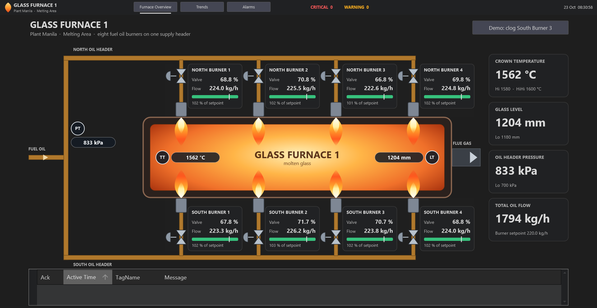
The screens
Furnace Overview
The start screen. The furnace is drawn in plan view with the molten glass in the centre, the four north burners along the top and the four south burners along the bottom. Brown lines are the oil piping: the supply enters on the left, feeds the header with its pressure transmitter (PT), and branches to every burner. Each burner shows its control valve, a flame that is lit while oil flows, its valve opening, its oil flow, and a bar of the flow against the setpoint. The white tick on the bar marks 80 % of the setpoint, the clogging limit. The cards on the right show crown temperature, glass level, header pressure and total oil flow, and the active alarm list runs along the bottom. Clicking a burner opens its detail window with a trend of valve opening against oil flow.
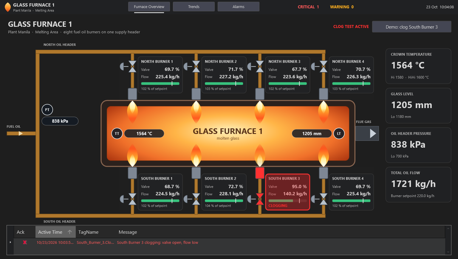
Clog test
The button Demo: clog South Burner 3 forces South Burner 3 to the values seen on site during a clog: valve at 95 % and flow at 140.2 kg/h. The clogging flag sets, the Critical alarm appears in the header count and in the alarm strip, and the burner's valve, nozzle and card turn red and blink.
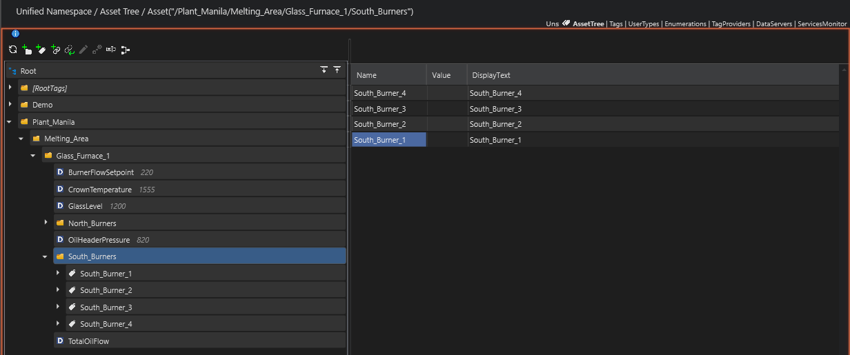
Asset model in the Designer
The Unified Namespace follows the ISA-95 path from the IO list: Plant_Manila / Melting_Area / Glass_Furnace_1 / North_Burners | South_Burners / <Burner>. The furnace measurements, the burner flow setpoint and the calculated total oil flow sit at furnace level. Each burner is an instance of the Burner UserType.
The solution also includes a Trends screen (oil flow of the eight burners on one chart, crown temperature on another) and an Alarms screen (active alarms and 24-hour alarm history), reached from the header.
Architecture Summary
Module | Objects | Description |
|---|---|---|
UNS (Tags) | 1 UserType, 16 tags | Burner type (ValveOpening, OilFlow, Clogging); 8 burner instances, 5 furnace-level tags, 3 demo tags |
Devices | 1 channel, 1 node, 19 points | ValueSimulator: each signal is a sine wave between the IO list's Sim Min and Sim Max. The PLC (Modbus TCP) is listed for reference and not configured. |
Scripts | 11 expressions | Clogging flag per burner, total oil flow, and the South Burner 3 clog test routing |
Alarms | 12 items, 2 groups | 8 burner clogging (Critical), crown temperature Hi / HiHi, glass level Lo, oil header pressure Lo |
Historian | 1 table, 20 tags | Every burner's valve opening and oil flow plus the four furnace values, saved on change |
Displays | 12 displays, 1 layout | Header, Furnace Overview (start), Trends, Alarms and one detail popup per burner (the template's default pages are kept alongside) |
Clogging rule
Each burner has a calculated Clogging flag, implemented as one expression per burner:
Clogging = Valve Opening >= 90 %  AND  Oil Flow < 80 % of the Burner Flow Setpoint

IIf(Tag.Plant_Manila/Melting_Area/Glass_Furnace_1/South_Burners/South_Burner_3.ValveOpening >= 90
    AndAlso Tag.Plant_Manila/Melting_Area/Glass_Furnace_1/South_Burners/South_Burner_3.OilFlow
< 0.8 * Tag.Plant_Manila/Melting_Area/Glass_Furnace_1/BurnerFlowSetpoint, 1, 0) |
With the normal setpoint of 220 kg/h the flow limit is 176 kg/h. The normal simulation never reaches 90 % valve opening, so the alarm only fires during the clog test.
Try it yourself
- Open the solution and start the runtime. The Furnace Overview opens with all eight flames lit and no active alarms.
- Press Demo: clog South Burner 3. Watch South Burner 3 turn red and the Critical alarm appear.
- Click South Burner 3 to open its detail window and see the valve line climb while the flow line drops.
- Go to Alarms and press Acknowledge all. Press the clog button again to end the test.
Related
BytePizza AI Designer Example: a restaurant-operations solution built from two prompts.
PID Process Trainer AI Designer Example: a fired heater with three live control loops.