


Generates simulated values for solution testing
- Name: ValueSimulator
- Version: 1.0.1.1
- Protocol: Proprietary
- Interface: TCP/IP
- Runtime: .NET 10 (Multiplatform)
- Configuration:
- Devices / Protocols
Overview
The Value Simulator enables the simulation of a device connected to your solution that exchanges multiple data types with your application on the software platform. It allows configuration, management, and even more control for simulations and tests. It is a valuable tool for test tasks when developing your solutions
Communication Driver Information | |
|---|---|
Driver name | ValueSimulator |
Assembly Name | T.ProtocolDriver.ValueSimulator |
Assembly Version | 1.0.1.1 |
Available for Linux | Runtime only |
Protocol interface | Proprietary over TCP/IP |
Requirements | Ethernet port |
Configuration
New in 10.1.5
The Value Simulator ships with a refreshed Address editor inside the Designer Points table: each simulation type (BOOL, INTEGER, FLOAT, STRING, RAMP, SINE) now exposes a structured field set (Min / Max / Step / StringLength) instead of a free-text concatenated string, and validation is performed inline as you type. Existing addresses authored in earlier versions remain valid and continue to round-trip through the new editor unchanged — the underlying <Type>;<Min>;<Max>[;<Step>] syntax documented below is still the canonical storage form.
In the software platform, the Devices module manages communication with field devices through the Channels, Nodes, and Points by allowing stable and secure data exchange between multiple devices across different networks. Protocols define communication rules between the platform and devices. Channels define global parameters for the usage of a communication protocol. Nodes represent the physical field devices (like a PLC) with a unique field address (PrimaryStation). Points represent tags within a device. Additionally, AccessType defines how the device interacts with the platform (Read and/or Write).
All initial configurations for devices in the solutions on the software platform encompass the following workflow:
Channels
On the Designer workspace, navigate to Devices/Channels in Solution Explorer. Define a Channel using a target communication Protocol. This will create the base instance for linking a Node and does not require any additional configuration.
Nodes
On the Designer workspace, navigate to Devices/Nodes in Solution Explorer. Define the Node linked to the created Channel. It does not require additional configuration.
Points
On the Designer workspace, navigate to Devices/Points in Solution Explorer. Define the Point you would like to monitor. The Point controls the behavior of simulated data. You must map the Tag object to Point. After that, it requires the Address configuration.
Address
To configure a point, navigate to Devices > Points, then click on the Address column to edit it. Use the following syntax for the Address:
<Type>;<Min>;<Max>
<Type>;<Min>;<Max>;<Step>  (Only for RAMP type)
<Type>specifies the simulation type:BOOL,INTEGER,FLOAT,STRING,RAMP, orSINE. From FrameworX 10.1.6a, the address can also be a function, described in Function addresses below.<Min>and<Max>define the minimum and maximum values for the simulation.<Step>(only used with theRAMPtype) is the number added to the value each time the point is read, which is once per read polling period of the point’s AccessType.
From FrameworX 10.1.6a, Min, Max and Step accept decimals, written with a dot as the decimal separator, for example FLOAT;70.5;95.5;1 or RAMP;0;1;0.1. An address with a non-numeric Min, Max or Step, for example RAMP;abc;def;1, is invalid. The point is left out of communication, its tag does not report Good quality, and the Devices trace in the Trace Window reports the address as invalid.
For the STRING type, you can specify a custom StringLength to control the length of the generated string according to your requirements.
Function addresses
From FrameworX 10.1.6a, a point address can be a function written as name(argument, argument, ...). The function name ignores letter case, arguments are separated by commas, and an empty numeric argument takes its default. Numbers use a dot as the decimal separator. A function address contains no semicolon or colon. Periods are in seconds. The address dialog in the Points table shows the fields of the selected function.
Function | Defaults | Value |
|---|---|---|
| 0, 100, 10 | A sine wave between min and max, one cycle every period seconds, starting at the midpoint. |
| 0, 100, 10 | A cosine wave between min and max, one cycle every period seconds, starting at max. |
| 0, 100, 10 | Max for the first half of each period, then min for the second half. |
| 0, 100, 10 | Rises from min to max and returns to min within each period. |
| 0, 100, 10 | Rises from min to max over the period, then starts again at min. |
| 100, 1.2, 0.06, 0.25 | A process value that starts at 0 and settles on the setpoint the way a PID-controlled process does. |
| 0, 100 | A random value between min and max. |
| period 1, repeat true | Steps through the values in order, one every period seconds. With repeat=false the last value is held. A value can be a number, true or false, or text, and text in double quotes can contain commas. |
| quality Good | A fixed value with the chosen quality: Good, Bad or Uncertain. Useful for testing quality displays and alarms. |
| A fixed value. A write replaces it, and later reads return the written value. | |
| A fixed value that writes leave unchanged. |
RAMP, SINE and INTEGER behavior
From FrameworX 10.1.6:
A RAMP point starts at Min. Each later read adds Step.
With a Step of 0 or more, a read whose value would pass Max returns Min instead, so the value never goes past Max. For example,
RAMP;0;100;7goes from 98 back to 0, andRAMP;0;179;13goes from 169 back to 0.A Step of 0, or a Step larger than the range between Min and Max, keeps the value at Min.
A negative Step lowers the value at each read, with no lower limit.
Each RAMP or SINE point progresses on its own, also when several points share one channel.
INTEGER random values include Max, and random points read at the same time return independent values.
Changed in FrameworX 10.1.6
Value Simulator points behave differently after an upgrade from 10.1.5:
From FrameworX 10.1.6a, a decimal Min, Max or Step is used as written, so
FLOAT;70.5;95.5;1runs from 70.5 to 95.5. In 10.1.5, the decimal part was dropped, so the same address ran from 70 to 95.From FrameworX 10.1.6a, an address written as a function name followed by parentheses, such as
SINE(x), is read as a function address and uses the form described in Function addresses.When Step does not divide the range evenly, RAMP returns to Min instead of publishing one value above Max. In 10.1.5,
RAMP;0;100;7published 105 before it returned to 0. Review displays, alarm limits and tests built on the old sequence.In 10.1.5, the RAMP points of a channel shared one counter, and so did the SINE points. From 10.1.6, each point keeps its own sequence.
Points configurations examples
TagName | Node | Address | DataType | AccessType | Modifiers |
|---|---|---|---|---|---|
MySine | SimulatorNode | SINE;-50;50 | Native | Read | |
MyRamp | SimulatorNode | RAMP;0;100;10 | Native | Read | |
MyRamp2 | SimulatorNode | RAMP;0;179;13 | Native | Read | |
MyString | SimulatorNode | STRING; | Native | Read | StringLength=5 |
MyBool | SimulatorNode | BOOL; | Native | Read | |
MyInt | SimulatorNode | INTEGER;0;10 | Native | Read | |
MyFloat | SimulatorNode | FLOAT;-500;-100 | Native | Read | |
MyDecimal | SimulatorNode | FLOAT;70.5;95.5 | Native | Read | |
MySineWave | SimulatorNode | sine(0,100,60) | Native | Read | |
MyCosineWave | SimulatorNode | cosine(0,100,60) | Native | Read | |
MySquareWave | SimulatorNode | square(0,1,10) | Native | Read | |
MyTriangleWave | SimulatorNode | triangle(50,55,10) | Native | Read | |
MyRampWave | SimulatorNode | ramp(0,100,30) | Native | Read | |
MyLevel | SimulatorNode | realistic(75,1.2,0.06,0.25) | Native | Read | |
MyRandom | SimulatorNode | random(10.5,20.5) | Native | Read | |
MyMode | SimulatorNode | list(Hand,Off,Auto,period=5) | Native | Read | |
MyBadValue | SimulatorNode | qv(42,Bad) | Native | Read | |
MySetpoint | SimulatorNode | constant(50) | Native | ReadWrite | |
MyFixed | SimulatorNode | readonly(50) | Native | Read |
Result example
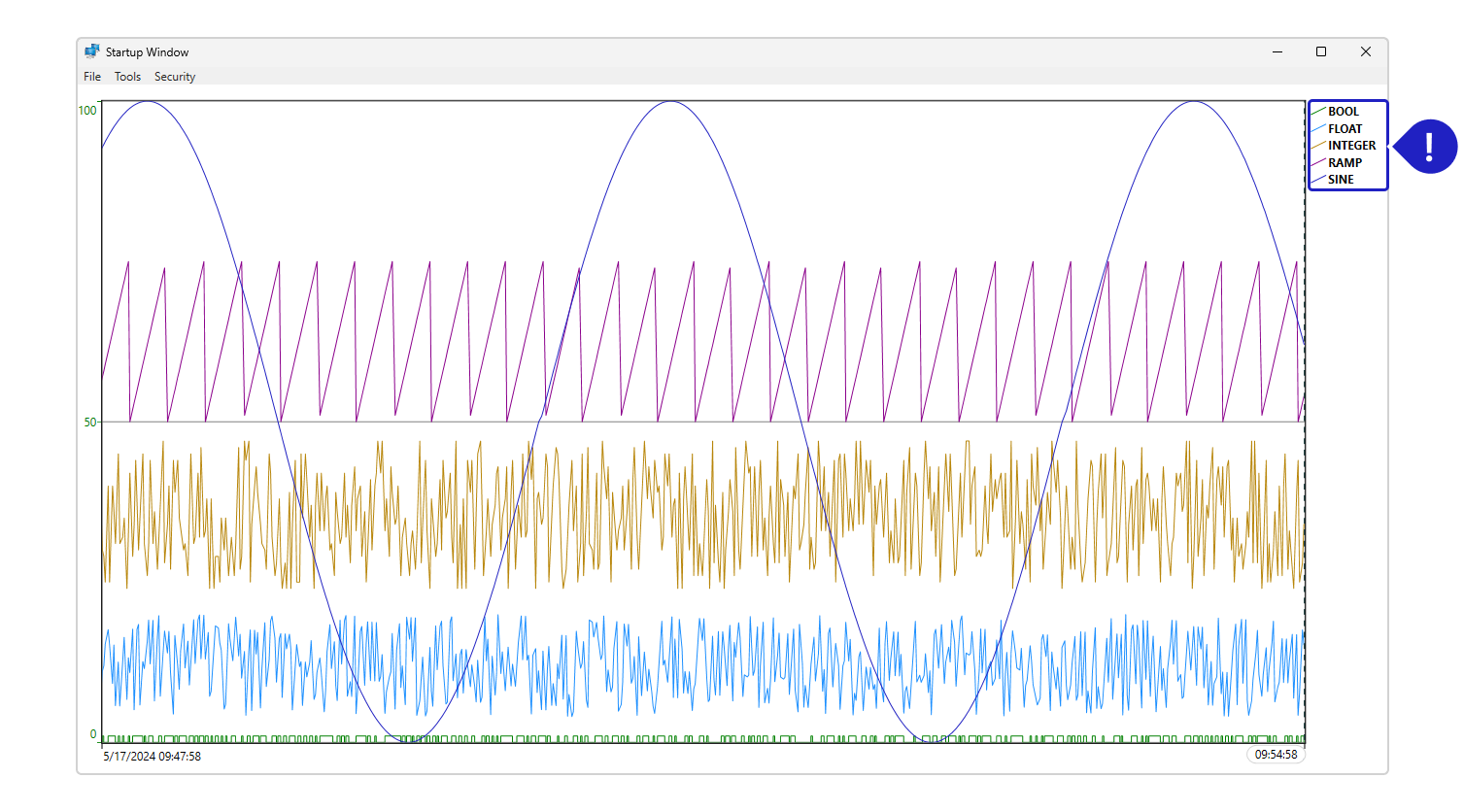
All type values are plotted in the trend chart below for clearer visualization.
Diagnostic Tools
Diagnostics tools refer to the Property Watch, Trace Window, and Module Information. These tools identify communication blocks and address errors, allow property access to pinpoint error causes, and display system messages for device management and troubleshooting, offering a comprehensive approach to device management and troubleshooting for Solutions on the software platform.
Module Information
This tool provides insights into module operations and communication channels, offering information about virtual reading groups, error codes, and communication events. It helps users identify communication blocks and effectively address errors in industrial automation systems.
Property Watch
This tool enables users to access, read, and write tags and internal properties of the system. It assists in identifying the root cause of errors through negative error codes, allowing for real-time adjustments and optimizations to the system configuration.
Trace Window
This tool displays system messages in a data grid interface, providing information about the status of reads, writes, and communication frames. It is particularly useful for various PLCs and communication protocols, as it presents invalid addresses in the configuration, assisting in device management and troubleshooting.
Driver Revision History
Version | Notes | Updated |
|---|---|---|
1.0.0.1 | Initial release published according to new documentation standards. | February, 2023 |
1.0.0.3 | Update Ramp with Step parameter. | June, 2024 |
1.0.1.0 | New structured Address editor in Designer (per-type Min/Max/Step/StringLength fields with inline validation); .NET 10 runtime compatibility fix. | May, 2026 |
1.0.1.1 | The Value Simulator can now act as a UNS Tag Provider with a built-in set of 15 simulated tags; new point functions: sine, cosine, square, triangle and ramp waves with a period in seconds, a realistic value that follows a setpoint, random, value lists, a chosen quality, and constant (writable) or read-only values; Min, Max and Step accept decimals (previously truncated), and a non-numeric value now marks the point Bad instead of silently reading 0; RAMP starts at Min, INTEGER can reach Max, and each point keeps its own sequence instead of sharing it with other points on the channel; the address editor shows only the fields of the selected type, keeps the values you type and no longer rewrites the address when opened. | October, 2026 |
In this section...