


Clients compatible with OPC UA specification.
- Name: OPCUAServerSimulator
- Version 1.0.0.0
- Protocol: OPC UA
- Interface: TCP/IP
- Runtime: Multiplatform
- Configuration:
- DataExplorer / MQTT
Overview
The OPC UA Server Simulator is a built-in tool of the software platform that emulates the behavior of an OPC UA server. It exists to facilitate the testing and development of OPC UA client applications in the absence of physical hardware.
The simulator generates a hierarchical address space for clients to interact with. Potential uses include testing client functionality, prototyping data models, and experimenting with OPC UA communication patterns. Users can configure server settings, define the data structure, and launch the simulator through its graphical interface or by using command-line parameters. Once running, OPC UA clients can discover and connect to the simulator as they would with a real OPC UA server.
This page contains information on the OPC UA Server Simulator Configuration and Runtime behavior.
The OPC Simulator can be Started from the DataExplorer User interface, or running its executable directly with the proper command line parameters.
When running, it will create an OPC UA server, populating the Address Space with simulated data. From the client point of view, the OPC Simulator, will just be found and act as it was any other OPC UA server.
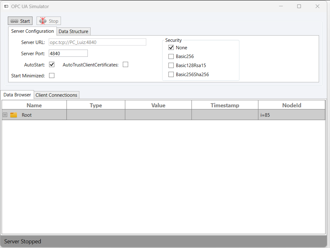
Simulator Configuration
The OPC UA Server Simulator is divided in two main regions. Configuration (customize Server settings and DataStructure) and View (DataBrowser and Client Connection List).
Server Configuration
The Server Configuration component enables users to customize server-specific settings.
Server URL: Read-Only field, indicating the communication endpoint URL for Client-Server interactions. It is composed by the localhost address and Server Port field.
Server Port: Defines the OPC UA Server port to be used as Server URL.
Security: Defines which security policies will be enabled in the Server
None.
Basic256
Basic128Rsa15
Basic256Sha256
AutoStart: OPC Server is started automatically (valid for the next time the application is started).
Start Minimized: Application starts minimized (valid for the next time the application is started).
Auto Trust Client Certificates: Server will automatically trust incoming connections using security. If False, a popup window will appear, so the user can choose to Trust or Reject the Client certificate
Use the Trust button to allow the Client connection, or Reject to block it.
You can store the OPC Client in the Server’s trusted list, enabling the Save to Trust List CheckBox.
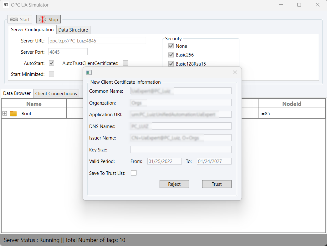
The fields can only be modified while the OPC Server is not running.
Data Structure
In this tab, you will be able to configure the Data Structure for the OPC Server address space.
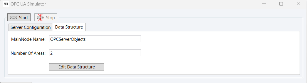
The structure is defined based on a hierarchical structure that is illustrated below.
<MainNodeName> |-- Area1 | |-- Device1 | | |-- Var1 | | |-- ... | | |-- VarN | |-- Device2 | | |-- Var1 | | |-- ... | | |-- VarX |-- Area2 |-- Device1 | |-- Var1 |-- Device2 |-- Var1
To edit the structure, click on the Edit Data Structure and customize your OPC Server structure at the dialog window.
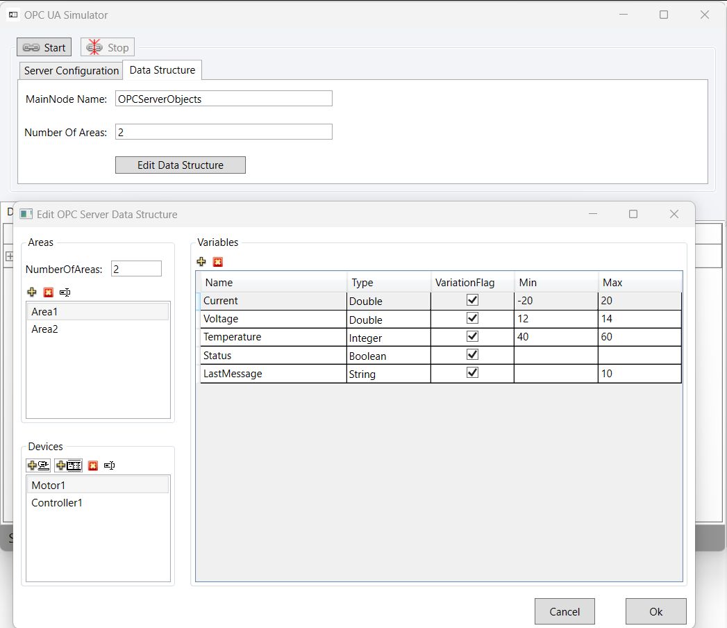
There are some properties to be defined for Variables:
Type: Define the Variable DataType. Options are:
Double
Integer
Long
Boolean
String
VariationFlag: Flag that indicates if variable value will be simulated every second in Runtime.
Min: Defines the minimum value for simulated data.
Max: Defines the maximun value for simulated data.
The DataStructure can only be edited while the OPC Server is not running.
Data Browser
In this region, you will be able to see the OPC Server Address space in a TreeView structure.
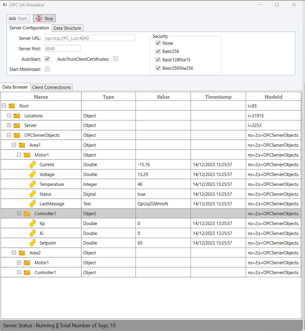
The TreeView connects only to the OPC Simulator. It cannot be used to connect to other OPC Servers.
Client Connections List
In this tab, you can monitor the clients that are/were connected to the OPC Server.
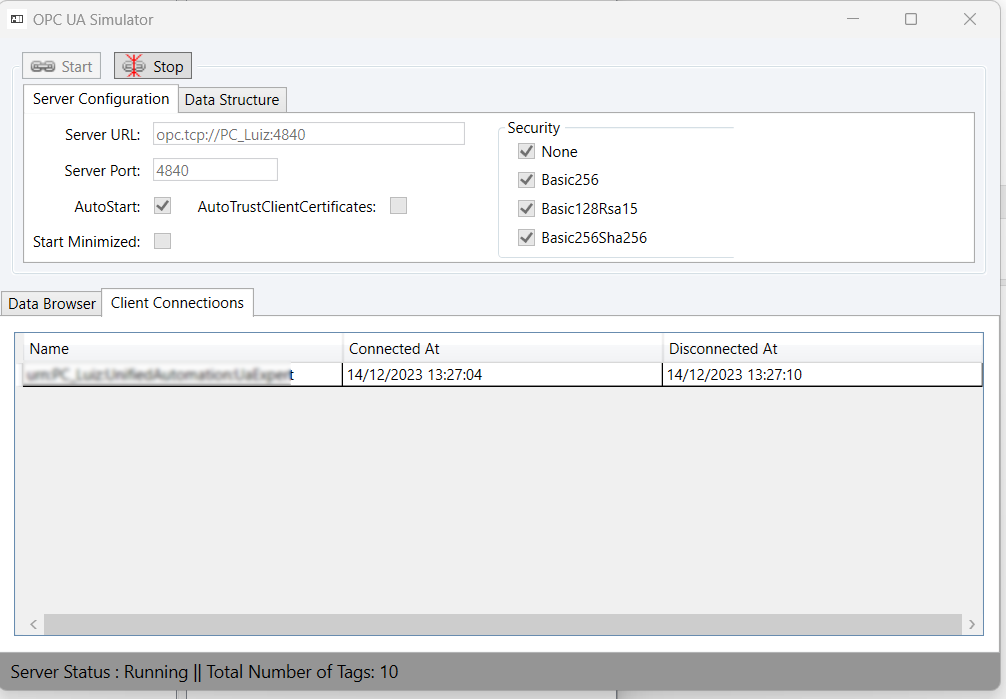
Where:
Name: Name of the Client’s session.
Connected At: DateTime the Client connected to the Server.
Disconnected At: DateTime the Client disconnected from the Server. The Client Connections list is cleared if the OPC Server is stopped.
Command Line Parameters
The OPC Simulator can be executed with custom parameters through the command line. The syntax is as follows:
"..\OPCUASimulator.exe" /param1:<param1Value> ... /paramN
The existing parameters are listed below:
- Minimized: Application starts minimized.
- AutoStart: OPC Server is started automatically.
- AutoTrustClientCertificates: Server will automatically trust incoming connections using security. If False, a popup window will appear, so the user can choose to Trust or Reject the Client certificate
- Port: Defines the OPC UA Server port to be used as Server URL.
- Config: Full path for *.xml configuration file with Server Configuration and custom DataStructure. More details on the syntax for the *.xml file in section 4.
- Path: Full path of a FrameworX solution directory in which a configuration file can be found
- Areas:
/areas:<count>adds generated areas to the address space for scale tests. Available from FrameworX 10.1.6. See Scale and Outage Testing below. - Outage:
/outage:<up>,<down>[,<initialDelay>[,<cycles>]]turns on the outage timetable, with times in seconds. Available from FrameworX 10.1.6. See Scale and Outage Testing below.
Usage:
"..\OPCUASimulator.exe" /Minimized /AutoStart
                         /Config:"C:\Documents\CustomSource.xml"
The input parameters are not case-sensitive
Custom Configuration (*.xml)
With a custom configuration file, you will be able to define your own OPC Server Configuration and DataStructure. The syntax for the configuration is described below:
<?xml version="1.0" encoding="utf-8" ?>
<OPCServerConfiguration>
	<SimulatorControl>
		<ServerPort>4840</ServerPort>
		<AutoStart>false</AutoStart>
		<Minimized>false</Minimized>
		<AutoTrustClientCertificates>false</AutoTrustClientCertificates>
		<SecuritySettings>
			<None>true</None>
			<Basic256>false</Basic256>
			<Basic128Rsa15>false</Basic128Rsa15>
			<Basic256Sha256>false</Basic256Sha256>
		</SecuritySettings>
	</SimulatorControl>
	<DataStructure>
		<Node Name="OPCServerObjects">
			<Node Name="Area1">
				<Node Name="Motor1">
					<Variable Name="Current" Type="Double" VariationFlag="true" Min="-20" Max="20"/>
					<Variable Name="Voltage" Type="Double" VariationFlag="true" Min="12" Max="14"/>
					<Variable Name="Temperature" Type="Integer" VariationFlag="true" Min="40" Max="60"/>
					<Variable Name="Status" Type="Boolean" VariationFlag="true"/>
					<Variable Name="LastMessage" Type="String" VariationFlag="true"/>
				</Node>
				<Node Name="Controller1">
					<Variable Name="Kp" Type="Double" VariationFlag="false" Min="0" Max="50"/>
					<Variable Name="Ki" Type="Double" VariationFlag="false" Min="0" Max="100"/>
					<Variable Name="Setpoint" Type="Double" VariationFlag="false" Min="60" Max="65"/>
				</Node>
			</Node>
			<Node Name="Area2">
				<Node Name="Motor1">
					<Variable Name="Current" Type="Double" VariationFlag="true" Min="-20" Max="20"/>
				</Node>
				<Node Name="Controller1">
					<Variable Name="Kp" Type="Double" VariationFlag="false" Min="0" Max="50"/>
				</Node>
			</Node>
		</Node>
	</DataStructure>
</OPCServerConfiguration>
Scale and Outage Testing
Available from FrameworX 10.1.6. The simulator scales its address space to thousands of variables and goes offline on a timetable, so long-running stability tests and reconnection tests run against it unattended, with no external OPC UA server. Both options are off by default, and an existing configuration file behaves as before.
Large Node Count
The ScaleProfile block adds AreaCount generated areas when the server starts. Each area holds a motor and a controller with 8 variables in total, so AreaCount 1000 gives about 8,000 variables. The maximum AreaCount is 2000. AreaNamePrefix sets the name of the generated areas. The generated areas exist only in memory and are not written to the configuration file.
Outage Timetable
The OutageSchedule block takes the server offline on a schedule. The server stays up for InitialDelaySeconds plus UpSeconds before the first outage. Each cycle then keeps the server unreachable for DownSeconds and reachable for UpSeconds. CycleCount 0 repeats the cycle without end. A CycleCount above 0 stops after CycleCount cycles and leaves the server up. Mode accepts StopServer.
During an outage the endpoint disappears from the network, and a client trying to connect gets a refused connection, the same failure a stopped server produces. While the simulator window is open, its status line reports each outage and each restore, with the time the restore took, and states when a restore runs longer than the down window. Each restore rebuilds the whole address space, so a restore with a large node count on a busy machine takes longer.
Configuration
Add both blocks inside SimulatorControl, after SecuritySettings:
<SimulatorControl>
	<!-- after <SecuritySettings> -->
	<ScaleProfile>
		<Enabled>false</Enabled>
		<AreaCount>0</AreaCount>
		<AreaNamePrefix>SoakArea</AreaNamePrefix>
	</ScaleProfile>
	<OutageSchedule>
		<Enabled>false</Enabled>
		<Mode>StopServer</Mode>
		<InitialDelaySeconds>0</InitialDelaySeconds>
		<UpSeconds>600</UpSeconds>
		<DownSeconds>60</DownSeconds>
		<CycleCount>0</CycleCount>
	</OutageSchedule>
</SimulatorControl>
The command line switches set the same values. /areas:1000 turns on ScaleProfile with AreaCount 1000. /outage:60,20,30,3 turns on OutageSchedule with UpSeconds 60, DownSeconds 20, InitialDelaySeconds 30 and CycleCount 3. The simulator saves the switch values to the configuration file in use, as it does for Port.
"..\OPCUASimulator.exe" /AutoStart /areas:1000 /outage:60,20,30,3
In this section...