


CODESYS compliant PLCs (controllers)
- Name: PLCHandler
- Version 1.0.0.1
- Protocol: Proprietary CODESYS
- Interface: TCP/IP
- Runtime: .NET 4.8 (Windows)
- Configuration:
- Devices / Protocols
Overview
Communication with CODESYS compliant PLCs (controllers)
The CODESYS PLC Handler communication driver is supported only in Windows Solutions.
Channel Configuration
Protocol Options
There is no channel configuration required for CODESYS PLC Handler Client channels.
The PLC Handler connection works only in Windows runtime since the protocol does not support multi-platforms. If you are using a MultiPlatform TargetPlatform, you can set up the PLC Handler channel to run remotely on a Windows machine. This ensures stable communication with the PLC while keeping the system compatible across different environments.
Info
The PLC Handler protocol uses the PLC Handler API provided by CODESYS. This protocol and its API require the CoDeSys tags to be exposed inside the PLC using the SymbolConfiguration method instead of the SymbolSet method. The latter will not work with this specific instance of CoDeSys communication because SymbolSet exposure is only available via OPC UA. To communicate with a CoDeSys device using SymbolSet, use our OPC UA protocol.
In recent CODESYS versions, the Add Symbol Configuration dialog has Support OPC UA features checked by default. That option turns on Symbol Sets, and the PLC Handler then fails to load the symbols. Clear Support OPC UA features when you create the Symbol Configuration. If it was already created with the option on, delete it and add it again with the option cleared, then download the application to the PLC.
Node Configuration
Primary Station
Stations syntax: <PLCAddress> ; <PLCPort> ; <ProtocolName>;<MotorolaByteOrder>;<GatewayAddress>;<GatewayPort>;<GatewayPassword>;
<GatewayDeviceProtocol>;<LogonName>;<LogonPassword>
Where :
<PLCAddress> = Logical address or node name of the PLC. CODESYS protocol address can be specified. But be careful, as these addresses are automatically generated, they may change if the network configuration of the communication partners changes. Therefore configuring the device name should be preferred.
<PLCPort> = Tcp/Ip port number. If not specified, the default value 11740 is used.
<ProtocolName> = Communication protocol to the PLC; the most important settings are:
- Tcp/Ip (Level 4): TCP/IP Level 4 Protocol
- Tcp/Ip (Level 2): TCP/IP Level 2 Protocol
- Tcp/Ip (Level 2 Route): TCP/IP Level 2 Route
- Serial (RS232): Serial connection
- Simulator: Built-in software PLC for testing, with no controller. Available from FrameworX 10.1.6. See Built-in Simulator below.
<MotorolaByteOrder> = Byte order of the PLC.
<GatewayAddress> = If 'Tcp/Ip' is used as Gateway protocol: IP-Address or Hostname of the Gateway. If 'NamedSharedMemory' is used as Gateway protocol: Name of the shared memory on which the Gateway listens. If not specified, then the default name for the shared memory is used and it behaves identical to the protocol 'SharedMemory'. 'NamedSharedMemory' is for special use only.
<GatewayPort> = If 'Tcp/Ip' is used as Gateway protocol: Port number of the Gateway. Typical values: 1210 / 1217. All other configurations: Not evaluated
<GatewayPassword> = If the Gateway, which is used for the connection, protected by a Gateway password, than this can be entered here, to allow the PLCHandler to use this Gateway.
<LogonName> = If the user management is activated on the PLC, then the user name for the PLCHandler login can be specified here.
<LogonPassword> = If the user management is activated on the PLC, then the password for the PLCHandler login can be specified here.
Example: MY_PC_Name;11740;;False;localhost;1217;;;;;
Points Configuration
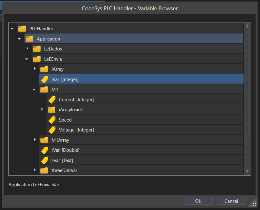
Choose the PLC Item that will communicate with the Project Tag. You can type the PLC Item name into the TextBox, or you can browse the PLC Items in the Cell Editor.
Troubleshoot
The status of the driver execution can be observed through the platform built-in diagnostic tools. Refer to the Using Diagnostic Tools topic in Devices Communication page.
Troubleshooting tips
In this driver, it is very important to enable the TraceWindow messages, as invalid addresses can cause all the communication block with the PLC to fail, the TraceWindow tool will display the first invalid address found on the block when the Device is enabled on the settings.
In order to have a quick view on the many communication blocks, open the ModuleInformation, navigate on the tree to find PLCHandler and then select Read Groups. Looking at the number and success and fail communication counters, you can easily identify if there is a block with error and then use the TraceWindow to locate the wrong address.
Common errors
Symptom | Cause | Fix |
|---|---|---|
Test in the import dialog or station editor returns | The connection and logon succeeded, but the PLC has no symbol table the PLC Handler can read. Either the Symbol Configuration was not downloaded, or it was created with Support OPC UA features, which exposes the variables through Symbol Sets. | Create the Symbol Configuration with Support OPC UA features cleared, select the variables, build, and do a full Login with download. A pending change shows in the Symbol Configuration editor as "Changed symbol configuration will be transferred with the next download or online change". |
Import and Test work in the Designer, but at runtime no value is read. The trace shows | The solution Target Platform is MultiPlatform (.NET). The PLC Handler runs only in the Windows (.NET 4.8) runtime. | Use a Windows (.NET 4.8) solution, or run the channel remotely on a Windows computer. See Remote Channels. |
Built-in Simulator
Available from FrameworX 10.1.6. The PLC Handler connector includes a software PLC. You configure, import, browse and run a PLC Handler channel with no controller, gateway or network.
- Set the station Protocol to Simulator. It is the last entry in the Protocol list, both in the station editor in Devices → Nodes and in the Codesys PLC Handler import dialog.
- Use the PLC Address field to size the catalog.
sim://5x10creates five simulated controllers with ten variables each, andsim://largecreates a large tag tree. A blank address, or any other value, starts a default catalog. - The Test button in the station editor reports OK with nothing connected.
The simulated controller exposes plain variables, one- and two-dimensional arrays, structures with their members, and arrays of structures. Tag import, browsing, reads and writes behave as they do with a real controller. Values change between reads and repeat the same sequence on every run, so test results are reproducible. A value written to a simulated variable reads back on the next read.
The Simulator protocol is set per station. Stations configured for real controllers keep their settings. The simulator tests the connector on the PC side and does not replace a test against a real CODESYS controller.
Codesys Simulated PLC - Installation and Getting Started
There is a software that can be used to program real PLCs or simulated ones, called CODESYS Control Win V3.
For more information on how to install and configure it, please refer to the Codesys documentation.
CODESYS Control Win V3 does not start
If the CODESYS Control Win V3 service fails to start with Windows error 1053, check the Windows System event log. A message such as "Application requires CodeMeter Runtime Modules with version 8.30.6885 or higher" means the installed CodeMeter Runtime is older than the one your CODESYS version requires. This can happen when another product installs an older CodeMeter kit over the one CODESYS installed. Install the current CodeMeter User Runtime for Windows from Wibu-Systems over the existing one, then restart the computer.
Driver Revision History
Codesys PLC Handler Driver Revision History | |
|---|---|
Version | Notes |
1.0.0.1 | Tag Provider performance with large CODESYS projects is much improved, the last tag of each read batch is no longer dropped, and browsing programs that contain arrays or function blocks no longer drops the connection; Import Tags no longer duplicates user-type members; Station editor keeps the configured protocol and gateway protocol, detects Motorola byte order regardless of casing and handles an empty network scan; new built-in Simulator protocol for testing without a controller; Test Connection says when it ran on the Designer computer instead of the runtime. |
1.0.0.0 | Initial release on new documentation standards |
In this section...